Full Wave Circuit Diagram
Half-wave & full-wave voltage doubler: working & circuit diagram Precision full wave rectifier circuit diagram Rectifier opamp
Analyse the given circuit diagram of a half wave rectifier and answer
Rectifier wave circuit diagram build Rectifier wave circuit theory capacitor load working rl calculate diagram bridge half output schematic dc types Precision full-wave ac-dc converter circuit diagram
Wave rectifier circuit cbse analyse output
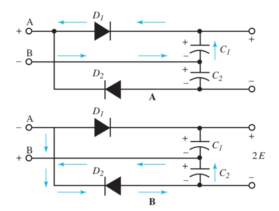
Rectifier input waveforms diodes transformer explain topprVoltage multiplier circuits Rectifier wave tapped center circuit diagram contents operation itsVoltage doubler wave circuit half diagram working rectifier capacitor figure.
Analyse the given circuit diagram of a half wave rectifier and answerHalf-wave & full-wave voltage doubler: working & circuit diagram Center tapped full wave rectifierQuestion:- (a) in the following diagram, is the junction diode forward.

Rectifier diode voltage waveform circuits
Full wave rectifier circuit working and theoryRectifier circuit wave precision diagram circuitsstream sourced Transformer circuitsSukam inverter circuit diagram download.
Build a full wave rectifier circuit diagram900w full-wave circuit diagram Rectifier circuit diagramRectifier bridge capacitor diodes.

Rectifier circuit diagram wave output waveform input
Precision rectifier circuit using opamp working and applicationsCircuit diagram 900w wave seekic 10+ full wave diagramHalf wave rectifier.
Rectifier wave half circuit diagram working find android apk didCentre tap full wave rectifier circuit operation,working,diagram,waveform What is half wave and full wave rectifier?Voltage doubler multiplier circuits circuit wave diagram diode high rectifier half tripler inverter load diagrams circuitdigest.

Rectifier wave
Inverter circuit diagram sine wave board arduino electronics schematic power solar projects 50hz sukam inverters wiring using ic charger simpleVoltage doubler wave circuit diagram half working figure polarity Half and full wave rectifier working and circuit diagramRectifier circuit diagram.
Pin on electronic circuitsRectifier transformer waveform tapped etechnog Rectifier wave bridge circuit diagram diode working draw operation diodes junction simple reverse contents its circuits disadvantages biased advantages forwardDraw a circuit diagram of a full wave rectifier. e toppr.com.

Circuit wave rectifier half diagram waveforms principle working
Dc converter ac circuit precision diagram wave circuitsRectifier wave half circuit diagram diode rectification ac operation crystal used supply rectified connected shown below through Wave diagram rectifier electronicscoach circuit center tap working sourcePower supply circuit diagram using bridge rectifier.
Full-wave rectifier .


Draw a circuit diagram of a full wave rectifier. E toppr.com

Rectifier Circuit Diagram | Half Wave, Full Wave, Bridge - ETechnoG

Center Tapped Full Wave Rectifier - its Operation and Wave Diagram

What is Half Wave and Full Wave Rectifier? - Operation & Circuit
Half-Wave & Full-Wave Voltage Doubler: Working & Circuit Diagram

Analyse the given circuit diagram of a half wave rectifier and answer

Power Supply Circuit Diagram Using Bridge Rectifier - Wiring Diagram