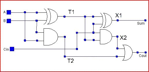
Full Adder Internal Circuit Diagram
Figure 1: schemaric of a full adder Adder circuit construction binary circuits qiskit sourav gupta Adder half circuit digital
Adder - Classifications, Construction, How it Works and Applications
Adder circuitverse Adder circuit Full adder circuit diagram
Adder circuit
Adder figure diagramHalf & full adders, design full adder using half adder Adder xor rangkaian transistor ripple pengertian kombinasiFull adder.
Adder circuit proposedWhat is half adder Adder circuit implementation addersNew full adder circuit.

Cd4008 4-bit full adder ic pinout, working, example and datasheet
Full-adder circuitBlock diagram of full-adder circuit Full adder circuit: theory, truth table & constructionFigure (3) full adder..
What is adder?Adder circuit diagram vhdl code Adder cmos circuit diagram transistor fa 28t transistors implementation edacafe using transmission gate power fig phdthesis www10 bookComplete circuit of the full adder using the newly proposed design. the.

Proposed full adder schematic diagram
Adder truth logic half sumador gates binario inputs datasheet combination suma microcontrollerslabAdder logic half implementation Circuits and arithmeticAdder half truth circuitdigest.
Adder representedFull-adder circuit, the schematic diagram and how it works – deeptronic Adder carry circuit sum implementation logic output electronics simplified two outputs tutorial combinational both shows below figure circuitsArithmetic circuits adder.

Full adder
Full adder circuit diagramFull adder circuit diagram Adder circuit schematic diagram12+ half adder schematic.
2.2: proposed full adder circuitCircuits adder arithmetic circuit Adder circuits electrical circuit figureAdder diagram circuit.

Edacafe: power, accuracy and noise aspects in cmos mixed-signal
Vhdl code and circuit diagram for full adderDigital electronics arithmetic circuits Adder circuit.
.

VHDL Code and circuit Diagram For Full Adder - Engineering-Notes

Full Adder - Computer Organization And Architecture Tutorials - Teachics

Block diagram of full-adder circuit | Download Scientific Diagram

Full-Adder Circuit, The Schematic Diagram and How It Works – Deeptronic

EDACafe: Power, accuracy and noise aspects in CMOS mixed-signal

Full Adder Circuit Diagram

CD4008 4-Bit Full ADDER IC pinout, working, example and datasheet