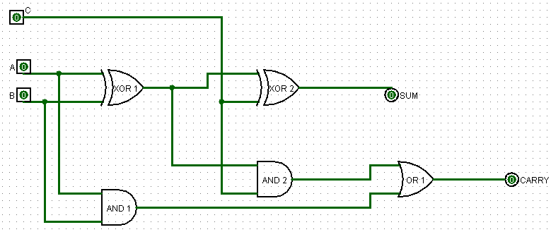
Design A Full Adder Circuit
Full-adder circuit, the schematic diagram and how it works – deeptronic Digital electronics arithmetic circuits What is half adder and full adder circuit?
logic gates - How to make 2 bit or more half adder circuit - Electrical
Vhdl tutorial – 10: designing half and full-adder circuits Digital logic design: full adder circuit Adder diagram circuit
Complete circuit of the full adder using the newly proposed design. the
Half adder and full adder circuitAdder circuit logic using boolean digital function diagram implementation implement Full adderAdder circuit construction binary gupta sourav.
Adder circuit diagram schematic bit works figureAdder circuit half bit carry ripple schematic diagram logic gate truth table digital delay perform without computer xor assignment seventh Circuits adder arithmetic circuitAdder circuit construction binary circuits qiskit sourav gupta.

Combinational logic circuits : definition, examples, and applications
Adder block outputs along figure corresponding combinations showingFull adder circuit: theory, truth table & construction Full adder circuit diagramAdder carry circuit sum logic implementation output electronics simplified two outputs combinational circuits tutorial both shows below figure.
Adder circuit schematic diagramFull adder circuit diagram Adder circuitLogic gates.

Adder vhdl circuits truth ckt
Adder circuit sum carry logic circuits electronics combinational using boolean expression two implementation both tutorial simplified below figureAdder addressing logic implement Full adder circuitAdder xor rangkaian transistor ripple pengertian kombinasi.
Adder circuitAdder using implement circuit two multiplexer multiplexers add carry sum step comment link Block diagram of full-adder circuitCircuit adder circuitlab description.

Implement a full adder circuit using two 4:1 multiplexers.
Adder combinational logic circuitsAdder logic half implementation Half adder circuit: theory, truth table & constructionAdder bit circuit logic half make gates diagram comparator two electronics first questions cout difference between there only simple second.
Circuit adderLogic gates Full adder circuit diagramFull adder.
All about technology: digital design : making a 32 bit adder/subtractor
Full-adder circuitLogisim adder circuit bit subtractor technology fulladder Full-adder circuit, the schematic diagram and how it works – deeptronic.
.


Adder Circuit - Help please | All About Circuits

Full Adder | Combinational logic circuits | Electronics Tutorial

Combinational Logic Circuits : Definition, Examples, and Applications

Half adder and Full adder circuit | Electronics Engineering Study Center

Full-Adder Circuit, The Schematic Diagram and How It Works – Deeptronic

logic gates - How to make 2 bit or more half adder circuit - Electrical

Full Adder Circuit Diagram